AOI Systems provided by ASC International employ a number of unique and innovative lighting technologies and algorithm-based tools to eliminate escapes and reduce false call rates.
Imaging Technologies - AOI
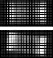
Image Matching
The high resolution color camera captures the image of the components and then through a series of algorithms determines if the components are acceptable based upon features such as image size, position, brightness and pasting angle.
Statisitical Image Modeling
Images are compared to a large library of master images collected during the "learn mode" in order to provide as many possible variations as associated with the component manufacturing process.

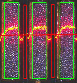
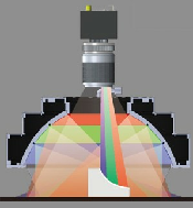
Optical LED Analytics
Using a high resolution color camera along with LED lighting and RGB principles, images are analyzed based upon reflection, refraction and angular refelection characteristics.

.png)
Line Scan Technology
Line Scan Technology is what separates SAKI from other AOI systems. Using a linear CCD array, the whole PCB can be scanned at high speed. For example, a 460 x 500 mm (18” x 20”) board can be scanned in less than 10 seconds. For AOI systems that capture multiple fields of view (FOV), time for image capture depends on the number of components to be inspected. This can cause a drastic increase in inspection time. Using SAKI’s Line Scan Technology, the number of components inspected has no bearing on cycle time. In addition, since the whole PCB image is captured, the whole PCB can be inspected for random and foreign debris – such as solder balls, loose parts, etc.
Coaxial Lighting and Telecentrics Optics
By employing Coaxial lighting techniques and Telecentric optics SAKI AOI products obtain clear, distortion-free images. Unlike conventional AOI systems that use a ring light surrounding the camera lens to project lighting at an angle, SAKI’s optical design uses a one-way mirror to enable light to be projected perpendicular to the surface. This lighting technique creates an excellent environment for solder inspection, since great differences are created when a good solder fillet is present and when it is not. In addition, perpendicular lighting reduces blind spots or shadowing – when a larger component creates a shadow over a smaller component.
Telecentric optics also help to eliminate blind spots and optical distortion. Optical distortion can reduce the effectiveness of an inspection library, since there may be a possibility that – due to varying degrees of optical distortion – a component’s library cannot be applied to the same component placed in another location. SAKI’s unique telecentric optical design increases the camera’s depth-of-field while maintaining a crisp, clean image.
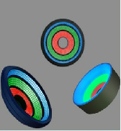
Using Various Lighting Schemes
SAKI AOI systems obtain over 20 difference lighting schemes in a single scan using SAKI’s original LED Control Alternative Scanning Technology. During a scan, the light from approximately 3000 LEDS is modulated several thousand times a second, while three projection angles – Top, Side and Low – are captured at the same time. Users then choose the best lighting for the desired inspection task.